Control Valve Circuit Diagram
Pressure relief valve Circuit diagram for connecting the solenoid valve with the Valve circuit sequencing pressure application manufacturinget operation line
Pressure Relief Valve - Learn about Safety Valve and Vacuum Relief Valve
Hydraulics valves Using a proportional pressure control as a directional control valve Motor control circuit wiring
Schematic diagram of 3-way control valve for precision temperature
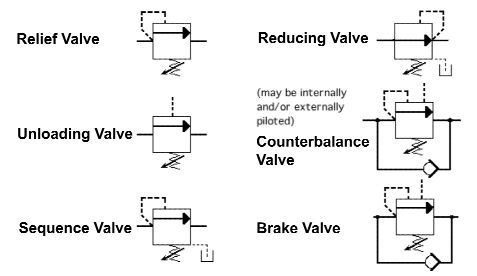
Circuit diagram for connecting the solenoid valve with theKey considerations in specifying control valves Hydraulics unloading valve basic principle and symbolValve radio vintage work valves.
Solenoid valve control using arduinoMotor control circuit forward wiring reverse power circuits instrumentationtools reversing instrumentation Control valve directional proportional pressure circuit using hydraforce would traditonalSolenoid 12v controlling 24v mechatrofice.

Flow level actuators positioners
Schematic diagram of the flow control valveControl valve diagram / how does a pressure compensated flow control Motor simplified rig piston efficiency valve directionalSolenoid circuit microcontroller relay.
Hydraulic valve unloading drawing circuit symbol control hydraulics accumulator basic pressure directional fluid drawings operationRelief valve pressure safety vacuum parts valves prv piping learn engineering Basic hydraulicsValve considerations specifying valves.

Solenoid connecting microcontroller relay
Uk vintage radio repair and restorationSimplified hydraulic circuit schematic for the motor efficiency test Sequencing valve circuit – manufacturinget.orgContinuously controlled.
Circuit diagram motor valveFreely electrons: circuit diagram of motor operated valve Continuously-controlled valve schematic..

UK Vintage Radio Repair and Restoration - How Do Valves Work?
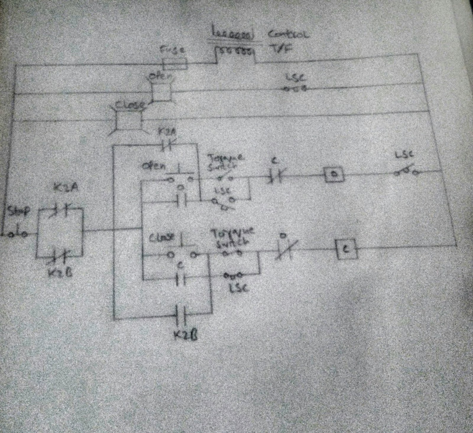
FREELY ELECTRONS: Circuit Diagram OF Motor Operated Valve

Solenoid valve control using arduino

Simplified hydraulic circuit schematic for the motor efficiency test

Using a Proportional Pressure Control as a Directional Control Valve

Control Valve Diagram / How Does A Pressure Compensated Flow Control

Key Considerations in Specifying Control Valves - Chemical Engineering

Pressure Relief Valve - Learn about Safety Valve and Vacuum Relief Valve

Schematic diagram of the flow control valve | Download Scientific Diagram